Hi, I have a question on class “A” surface, sure that sometimes the zebra stripes missaligned if you really-really look closely but is it still matter when it goes to production? does injection mold even if its gloss will not show this? i mean the productions will tolerate this and it doesnt matter anymore? i’ve seen people go crazy on this , I really want to know the profesionals opinions.
also, does anyone know what CAD ross lovegrove use for producing this cool stuff? also, fuseprojects, they use a lot of pattern which im curious how they do it on cad.
Zebra stripes are just one way of evaluating surface quality and more importantly boundary continuity. Ultimately how much they matter will depend on the part, the surface design, and the finish.
If you’ve ever seen junk surfaces, then the answer is “yes they matter”. If you’re designing a car, they matter. If you’re designing a pencil sharpener…well maybe.
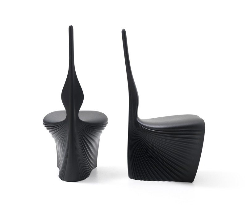
Not sure exactly how those forms were modeled, but it’s possible to get very organic forms like that by direct modelling in a surfacing tool (manually pushing/pullings CV’s to scuplt the surface) and it’s also possible they were sculpted in something like Zbrush or a subdivision modeller, exported as a rapid prototype/mesh, and then cast.
I was actually very curious about this since I had never compared a curvature-continuous surface next to one that wasn’t (although I had seen some zebra and in-program screenshots from the very helpful guides at SwTuts.com is for sale | HugeDomains — thanks to CADjunkie for showing me those when I needed Solidworks help in the past).
The first set of images are with a regular fillet, and the second set are with boundary surface blend between the two surfaces. Although reading the thread at SW Conic Fillets in 2014 I really want to try SW 2014 with the conic fillets.
I can see how they would definitely matter with a car, but it is hard to wrap my head around otherwise. In one example, I imagine making a rounded corner brick and then vacu-forming styrene over it … unless the fillets are really off, like not even tangent anymore, wouldn’t the way it is formed imply a curvature continuity anyway?
It is somewhat counterintuitive, but a smooth transition between an arc and a line is not smooth enough to create a seamless visual transition. Class A is simply the design of visible surfaces- and whether your surfaces transition as intended.
So in your vacforming example- if you can see abrupt changes of highlights then you need a smoother transition. Sometimes the product type allows manual finishing of the A surfaces- or you run the tooling at high temps to create a glossy surface with smoother transition- or you spec a satin finish which blurs the highlights so that Tangent continuous transitions are impercievable. CAD is only one tool- but if you have a large product or a glossy one where surface transitions are more apparent, then you want your software to control your highlight transitions.
From past videos Lovegrove favors working in Alias.
This Hermes watch is a painful example of tangent surfacing where it would have been much nicer with CC surfacing. You (highly trained industrial designer who does this sort of thing for a living) can literally see where the filets start and ends. It makes me a little sad.
I think that tangent continuity can be used to good effect. It can give a nice precise finish if used with intent. Some of these curvature continuous products can look over-designed.
There’s nothing wrong with G1 continuity, it’s all about understanding what the effects of using it are and where it becomes a problem. The nasty parts of G1 continuity (such as the really obvious highlights on the watch shown above) are areas where a little G2 love makes a world of difference. Just look at Apple products and you can see even on things like the cables or dongles they’ll have G2 continuity to keep it all looking smooth, even though to the rest of the engineering world it’s a “Rectangle with some fillets”.
A good analogy I’ve heard recently for handheld products is for transitions bigger than the wall thickness of a part, it’s worth building the transition G2 and for anything less you can get away with G1 rounds and no one will notice. Not an absolute, but probably a pretty good starting point for a lot of handheld type products.
I once witnessed an overseas vendor rebuild a CAD database I had done in Pro E using ONLY 2 degree surfaces (arc’s and straight lines) and rounds. Dimensionally they got the CAD within .1mm of the original database, but one look at the model in real life and you could tell how dramatic of a difference it was on the surfacing quality when there were horrible bone lines and tangency breaks across the major surfaces.
Just remember Class A is more than just unroken zebra stripes and curvature continuous fillets.
Smooth variation in curvature is required. The ‘rate of change’ changes at the same scale.
That’s why you’ll sometimes hear them referred to as monontone curves and surfaces